Wednesday, October 27, 2010

Don't buy Nikon software from imagemixer.net


About two years ago I decided to get Nikon Camera Control Pro 2. I found two sources that offered a downloadable version. The Nikon Mall and imagemixer.net. Since the Nikon Mall was (and still is) US only I ordered from imagemixer.net and was happy. I also updated Nikon Camera Control Pro several times without problems - until yesterday.

Yesterday when I tried to update the software to 2.8 the following message appeared:

The product key 40700-24986-02156-58340-44741 is unusable since it is not a genuine product key. Please purchase a genuine product key. If you see this message when you enter your product key, please contact your local Nikon office mentioned in the user's manual.


What a nice surprise. Suddenly I can't use the software any longer and I also can't use the previous version any longer.

I looked around and found an official statement from Nikon regarding this online company:

It has come to our attention that a website called “Imagemixer.net” is attempting to sell Nikon software keys. This web site is not an authorized dealer and is not affiliated with Nikon Inc. in any way. Nikon Inc. cannot assist with any license keys sold by this site and cannot replace any non-working keys without proof of purchase from an authorized dealer.
The only web site authorized to sell software keys alone (not boxed copies of software) is the Nikon Mall. ( http://www.nikonmall.com)"
To ensure that you receive a legal, authorized license key for Nikon software which Nikon Inc. can support please only purchase from an authorized dealer.

I bought an illegal software product without knowing it. If I want to use Nikon Camera Control Pro 2 I'm forced to buy it again from a Nikon authorized dealer.

As of today imagemixer.net is still offering Nikon software so hopefully this post will help others to stay away from this online store. I can only speak about Nikon software but obviously you should be also very cautious about the rest of their offer.

I fully understand why Nikon is taking action but I don't understand why imagemixer.net is still allowed to offer their software.

Most likely I will not buy the expensive software a second time and rather use the excellent and free Sofortbild app.

Thread at photocamel.com
Official Nikon statement
Another official Nikon statement
Sofortbild app

Update February 2011: All Nikon Sofware has dissapeared from the imagemixer website. I really hope Nikon has taken action and sued them. The thread at Photocamel also dissapeared. I'm very happy with Sofortbild and didn't miss Nikon Camera Control Pro so far.

Update December 2012: imagemixer.net sells Nikon software again. DO NOT BUY!!!.

Thread on flickr.com


Wednesday, March 24, 2010

Sennheiser MKE 400 + Canon 5D Mark II

The Canon 5D Mark II Firmware 2.0.4 finally allows manual control of the audio recording level in 64 steps. The audio preamp inside the Canon 5D Mark II is not the greatest but if you set the rec. level low i.e. 1, 2 or max. 3 steps above zero audio hiss practically disapears.

I find the Sennheiser MKE 400 signal at the "+" setting just a little too low to be used with the 1, 2 or 3 rec level of the camera. I didn't want to add a third battery to the system therefore I had the idea to boost the signal using an audio transformer. My solution boosts only one channel following an old sound recording trick. If you set one channel about 6 dB lower than the other you minimize clipped audio because when one channel clips you will most probably be able to use the -6 db one. Since the 5D Mark II doesn't show audio level meters during video recording such a safety net is very welcome.

I have no experience with audio transformers so I virtually tried my luck and bought a specs wise good looking shielded 1:2 audio transformer from RS-Components. The part number is 667-6044.
The shielded Z21805C 1:2 (6 dB) audio transformer is made by Oxford Electrical Products. Here's the data sheet. It has a very wide frequency range and low distortion and it doesn't add any noise. I think any quality transformer with similar specs will do.

I also bought a ready made stereo 3.5mm plug to socket cable and used a short piece of both ends.


To my surprise this simple solution works very well. Soundtrack Pro reports a 5 dB difference between the channels. The noise floor of a recording in an absolutely quiet room is at -65 dB at both channels (using rec. level 1 of the 5DMKII) and is practically not audible. It's a huge difference to the annoying hiss in the former AGC only recordings. I have no means to measure the audio quality but I can't hear any difference between the two channels other than the volume. For many applications this quality will be good enough and double sound is no longer mandatory.

Monday, March 15, 2010

Some interesting camera control projects

Open Camera Controller
A "hacked" Nintendo DS, the microprocessor chip of an Arduino board and a camera release cable are the main ingredients for this project.

OpenMoco
Open-Source Photographic Motion-Control

CAMremote-2
A small battery operated device controls many cameras via the USB port.

Friday, February 26, 2010

Control your camera by voice


Now this is fun. Did you know that every Mac comes with built-in speech recognition? Since all Apple laptops and the iMac come with a built in microphone you only need to know how to use AppleScript to voice control your camera using a Zephir or an Arduino I/O board.

You find the control panel under System Preferences- Speech. At first click on Calibrate ... to set the levels and train the system.


The following AppleScript listens for an hour for one of three keywords and starts or stops video or shoots a photo on one of the new Canon EOS DSLRs while you're hands are free to do other things. See previous posts for details on the Zephir.


tell application "ZephIR" to activate --get ZephIR ready
delay 2
tell application "System Events" to set visible of process "ZephIR" to false --hide ZephIR

repeat
try
tell application "SpeechRecognitionServer"
set command to listen for {"shoot photo", "shoot video", "exit"} giving up after 3600 --seconds
end tell
on error
display alert "Listening session timed out. Start script again."
return
end try

if command is "shoot video" then
tell application "ZephIR" to fire zephir command "START-STOP VIDEO" of component "Canon RC-1"
beep
else if command is "shoot photo" then
tell application "ZephIR" to fire zephir command "SHOOT PHOTO" of component "Canon RC-1"
else if command is "exit" then
delay 1
say "Good bye"
return
end if
end repeat


You can also demand a keyword (e.g. okay) before each command like okay shoot video, okay shoot photo and okay exit.

Tuesday, February 23, 2010

Controlling the Canon EOS Utility using AppleScript

The Canon EOS Utility is a great piece of software especially when you consider that it comes free with every Canon EOS DSLR. Its Remote Live View shooting window gives you a decent monitor image and lets you even start and stop video recording on all cameras that have the EOS Movie function.


The EOS Utility is not directly accessible using AppleScript but you still can control it using GUI scripting. The AppleScript below e.g. clicks on the "Prepare the camera for movie recording" button at the lower left corner of the Remote Live View window.

To find the pixel coordinates of a button press SHIFT COMMAND 4 on the keyboard. This activates the screenshot utility and if you place the cursor over a button you can see its pixels coordinates. Note the numbers and press ESC.

You must "Enable access for assistive devices" in System Preferences > Universal Access in order to use the scripts below.

Tested with OS X 10.4 and 10.5 only:
tell application "EOS Utility" to activate
tell application "System Events"
tell process "EOS Utility"
click at {38, 700} --x,y screen coordinates. 0,0 is at the upper left corner.
end tell
end tell


When you run this AppleScript (with the button coordinates of your screen!) you will notice the line
checkbox 1 of window "Remote Live View window" of application process "EOS Utility" of application "System Events"

in the "Result" area at the bottom of the Script Editor window. This is the actual AppleScript reference to this button that can be used in an AppleScript that is now independent of the window size of the EOS Utility.

tell application "EOS Utility" to activate
tell application "System Events"
tell process "EOS Utility"
click checkbox 1 of window "Remote Live View window" of application process "EOS Utility" of application "System Events"
end tell
end tell

Or just for fun the entire script in two command lines
tell application "EOS Utility" to activate
tell application "System Events" to tell process "EOS Utility" to click checkbox 1 of window "Remote Live View window" of application process "EOS Utility" of application "System Events"

The following script allows timed recordings:

on enable()
tell application "EOS Utility" to activate
tell application "System Events"
tell process "EOS Utility"
click checkbox 1 of window "Remote Live View window" of application process "EOS Utility" of application "System Events"
end tell
end tell
delay 1
end enable

on rec()
tell application "EOS Utility" to activate
tell application "System Events"
tell process "EOS Utility"
click checkbox 2 of window "Remote Live View window" of application process "EOS Utility" of application "System Events"
end tell
end tell
delay 2
end rec

enable()
rec()
delay 10 --record for 10 seconds
rec()
enable()


The next example clicks repeatedly on the <<< and >>> Focus buttons to simulate a focus pull from the background to the foreground and back again. It's not very smooth and repeatable though.


on enable()
tell application "EOS Utility" to activate
tell application "System Events"
tell process "EOS Utility"
click checkbox 1 of window "Remote Live View window" of application process "EOS Utility" of application "System Events"
end tell
end tell
delay 1
end enable

on rec()
tell application "EOS Utility" to activate
tell application "System Events"
tell process "EOS Utility"
click checkbox 2 of window "Remote Live View window" of application process "EOS Utility" of application "System Events"
end tell
end tell
delay 2
end rec

on focusNear3()
tell application "EOS Utility" to activate
tell application "System Events"
tell process "EOS Utility"
click button 8 of group 1 of window "Remote Live View window" of application process "EOS Utility" of application "System Events"
end tell
end tell
end focusNear3

on focusFar3()
tell application "EOS Utility" to activate
tell application "System Events"
tell process "EOS Utility"
click button 9 of group 1 of window "Remote Live View window" of application process "EOS Utility" of application "System Events"
end tell
end tell
end focusFar3

enable()
rec()
delay 3
repeat 4 times
focusFar3()
end repeat
delay 3
repeat 4 times
focusNear3()
end repeat
delay 3
rec()
enable()


Before you ask, yes I've tried to start movie recording and QuickTime audio recording at the same time via AppleScript. It works but it's impossible to get video and audio synced automatically. The delays are too long.

Sunday, February 21, 2010

Recording EOS movies with synced external audio -
A more dependable way

Requires an Arduino I/O board plus 180 ohms resistor and IR LED, an Apple computer with QuickTime Pro and an USB bus powered audio interface with phantom powered microphone inputs.

Calling the Zephir application from AppleScript (see previous post) added an unwanted delay. This solution is better since it uses the Arduino as an IR transmitter again. The response is much faster and both the QuickTime audio recording and the EOS movie recording stop at the same time. Occasionally there is a one frame inaccuracy but most of the time synchronisation is spot on if the track ends are aligned.


The AppleScript works like in the previous post but only has to send a character over the serial connection to the Arduino to start video recording. You need the free AppleScript extension SerialPort X to make it work.

(*
Simultanuously start and stop EOS movie and QuickTime audio recording.
EOS movie recording starts with a delay after receiving the remote signal but it stops at the same time as the audio recording.
To sync video and external audio align the track ends.
Requires an Arduino I/O board (arduino.cc) plus 180 ohms resistor and IR LED, an Apple computer with QuickTime Pro and an USB bus powered audio interface with phantom powered microphone inputs.
2010, Martin Koch, controlyourcamera.blogspot.com
*)
on countdown()
say "three"
delay 1
say "two"
delay 1
say "one"
delay 1
say "action"
end countdown

-- Uses SerialPort X from http://mysite.verizon.net/vzenuoqe/MacSoft.html
set portRef to serialport open "/dev/cu.usbserial-A6004byf" bps rate 9600 data bits 8 parity 0 stop bits 1 handshake 0
delay 2
if portRef is equal to -1 then
display dialog "Could not open serial port" buttons {"Cancel"} default button 1

else

tell application "QuickTime Player"
activate --get QuickTime Player ready
new audio recording --prepare new audio recording
end tell

tell application "Script Editor"
activate
display dialog "Start recording?" with title "EOS movie + QuickTime audio" buttons {"Cancel", "START"} default button 2
end tell

countdown()

serialport write "R" to portRef -- Write to Arduino to send EOS movie start/stop signal
tell application "QuickTime Player" to start first recording
beep

tell application "Script Editor" to display dialog "Stop recording?" with title "EOS movie + QuickTime audio" buttons {"STOP"} default button 1

serialport write "R" to portRef -- Write to Arduino to send EOS movie start/stop signal
tell application "QuickTime Player"
stop first recording
close first document
end tell

serialport close portRef

end if


The Arduino sketch continuously monitors the serial connection to the computer and sends the movie recording start signal if it receives the character R.

/*
Arduino sketch for simulating a Canon RC-1 remote control
Huge thanks go to http://www.doc-diy.net/photo/rc-1_hacked/index.php for figuring out the Canon RC-1 IR code.
2010, Martin Koch, http://controlyourcamera.blogspot.com
*/
#define irLED_EOS 11 // connect a IR LED with a 180 ohms resistor in series to digital pin 11
byte inbyte = 0;

void setup() {
pinMode(irLED_EOS, OUTPUT);
Serial.begin(9600); //open the serial port
}

void loop() {
inbyte = Serial.read();
if (inbyte == 'R') EOS_REC();
}


void EOS_REC() {
for(int count=0; count<16; count++) { //Burst 1
digitalWrite(irLED_EOS, HIGH);
delayMicroseconds(11);
digitalWrite(irLED_EOS, LOW);
delayMicroseconds(11);
}

delayMicroseconds(5360); //Pause

for(int count=0; count<16; count++) { //Burst 2
digitalWrite(irLED_EOS, HIGH);
delayMicroseconds(11);
digitalWrite(irLED_EOS, LOW);
delayMicroseconds(11);
}
return;
}

Wednesday, February 17, 2010

Recording EOS movies with synced external audio - The simple way

I found a very convenient way to get high quality synced audio. I tried this some time ago with my Canon 5D Mark II but gave up because I couldn’t get the external audio synched to the movie files. Now that I know that the 5D Mark II takes some time to actually start recording (when triggered via remote) I tried it again with success.

All that’s needed is a Zephir universal remote control, an Apple computer with QuickTime Pro and an USB bus powered audio interface with phantom powered microphone input(s) like e.g. the Alesis io|2 or a Shure X2U or a Centrance MicPort Pro.

To get the Canon RC-1 remote for the Zephir click on WebztIR in the Zephir application and navigate to Canon - Camera - Remote_RC_1. To make it compatible with the Applescript below rename the rather long video starting command to "START-STOP VIDEO".


Starting and stopping audio and video recording is done by AppleScript. Copy and paste the script below into the Script Editor and press the green run button. Note that there's no guarantee for the accuracy of AppleScripts delay command.


(*
Start and stop EOS movie and QuickTime audio recording.
EOS movie recording starts with a delay after receiving the remote signal but it stops at the same time as the audio recording.
To sync video and external audio align the track ends.
Requires a Zephir universal remote control (thezephir.com), an Apple computer with QuickTime Pro and an USB bus powered audio interface with phantom powered microphone inputs.
2010, Martin Koch, controlyourcamera.blogspot.com
*)

tell application "ZephIR" to activate --get ZephIR ready
tell application "System Events" to set visible of process "ZephIR" to false --hide ZephIR

tell application "QuickTime Player" to activate --get QuickTime Player ready
tell application "QuickTime Player" to new audio recording --prepare new audio recording

tell application "Script Editor" to activate
tell application "Script Editor" to display dialog "Recording" buttons {"Cancel", "START"}

say "three"
delay 1
say "two"
delay 1
say "one"
delay 1
say "action"
beep

tell application "ZephIR" to fire zephir command "START-STOP VIDEO" of component "Canon RC-1"
tell application "QuickTime Player" to start first recording

tell application "Script Editor" to display dialog "Recording ..." buttons {"STOP"}

ignoring application responses --don't wait until the Zephir action has finished
tell application "ZephIR" to fire zephir command "START-STOP VIDEO" of component "Canon RC-1"
end ignoring
delay 0.33 --alter this delay until the EOS movie and QuickTime recording end at the same time.
tell application "QuickTime Player" to stop first recording
tell application "QuickTime Player" to close first document


The AppleScript starts movie recording with the help of the Zephir universal remote control and uses the QuickTime Player to record an audio file at the same time.


The audio files are automatically saved at a location that can be determined with QuickTime Player > Preferences… - Recording. They are automatically named Audio.mov, Audio 1.mov, Audio 2.mov and so on. With the 5D Mark II file numbering set to “Auto reset” paired file naming can be achieved so finding the corresponding audio files is easy.


All that’s needed to sync the audio tracks is to align the track ends. AppleScript doesn't guarantee exact timing but I found that the synchronisation accuracy most of the time was high and repeatable.

I run the script without delay first and measured 10 frames difference between the audio spikes. At a frame rate of 30 fps one frame equals 1/30 = 0.033 seconds so since the external audio was 10 frames earlier a 0.33 s delay did the syncronisation.


The screenshot above shows the timeline zoomed in to a one frame level. As you can see the offset is really low and not audible. But since AppleScripts timing is not dependable such a synchronisation accuracy is not always the case.

If the audio sync is not perfect select the video track and press the . or , key to move the track by one frame until the audio waveforms line up.

Monday, February 15, 2010

Recording EOS movies with synced external audio

As long as you don’t film fine detail which causes heavy aliasing the current Canon DSLRs with EOS movie function record stunning images. The biggest flaw though is the audio automatic gain control (AGC) of those cameras. Whenever a scene is quiet the AGC pumps up the amplification of the microphone signal resulting in quite noticable noise hiss.

One solution to get high quality audio is to record it externally and sync the video and audio files later in the video editor. This means you have to start video and audio recording by pushing buttons on two different devices. It’s a hassle and you better not forget to turn on audio recording.
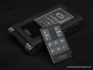

The Edirol R-09HR audio recorder has good internal microphones and records up to 24 bit/96 kHz audio. It also has 1/8” jack inputs for an external mic or line signal. But the best thing is that it comes with an infrared remote control.


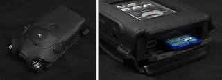
An optional leather cover offers a 1/4" mounting thread. I removed the back to get to the SD card more easily.


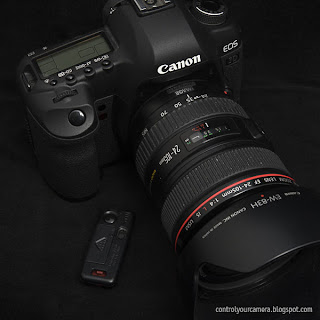
All current Canon DSLRs with EOS movie function allow starting and stopping video recording via an optional infrared remote control. Just switch the camera into Live View and use the 2s delay setting on the Canon RC-1 remote to start and stop video recording.


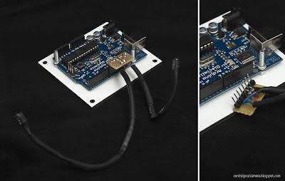
This project uses an Arduino I/O board and two IR LEDs to start recording on the Edirol R-09HR audio recorder and the camera at the same time.


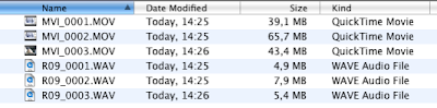
You can find the corresponding files with the help of the recording date but once you convert the h.264 files to lets say ProRes 422 files you’re altering the file date. A foolproof way is to set the cameras file numbering to “Auto reset” and the R-09HR audio recorder file naming to “Name”. This makes sure that file numbering starts with one on every blank storage card. Unfortunately the Canon EOS DSLRs do not differentiate between movie files and photo files so if you shoot photos make sure you also record a short audio file to keep file numbering paired.


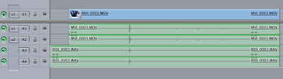
Although both devices receive the IR signal at practically the same time (with just a few milliseconds delay) the EOS movie recording starts with a quite long delay. Fortunately both stop recording at the same time so syncing is easy. All that’s needed to sync the audio tracks with one frame accuracy is to align the track ends.

Is the synchronisation accurate enough? Since the R-09HR STOP signal takes about 73 milliseconds and the EOS REC signal takes just about 6 milliseconds it makes sense to send the shorter signal at last i.e. the movie recording stops about 6 milliseconds later than the audio recording. To put this into perspective lets look at the approximate frame duration of video files. 24 or 25 fps equal roughly 40 milliseconds per frame and 30 fps equals about 33 milliseconds per frame. The 6 millisecond delay is therefore well within frame accuracy. You will hear the external sound within the same frame even when it comes 6 milliseconds before the audio recorded in the camera.


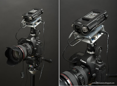
It looks weird but it gives me EOS movies with synced 24 bit/96 kHz audio.

Does this setup produce good sound? Not really, the internal microphones of the R-09HR are omnidirectional and pick up sound from everywhere. You usually want to capture the sound of the scene you're filming by placing a directional microphone close to the action. So for best sound connect an external directional microphone.
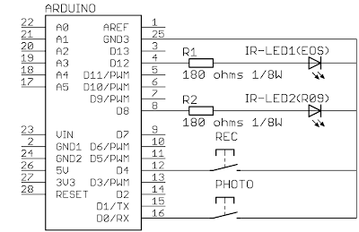


The circuit.


The Arduino sketch

/*
Arduino sketch for simulating a Canon RC-1 and EDIROL R-09HR IR remote control
2010, Martin Koch
http://controlyourcamera.blogspot.com/
Huge thanks go to http://www.doc-diy.net/photo/rc-1_hacked/index.php for figuring out the Canon RC-1 IR code.
IR signal sending code is based on an example at http://luckylarry.co.uk/2009/07/arduino-ir-remote-intervalometer-for-nikon-d80-that-means-timelapse-photography-yarrr
*/
#define irLED_EOS 12 // connect a IR LED with a 180 ohms resistor in series to digital pin 12
#define irLED_R09 8 // connect a IR LED with a 180 ohms resistor in series to digital pin 8
#define statusLED 13 // Built in LED on Arduino board
#define recBUTTON 4 // connect a push button to digital pin 4 and GND
#define photoBUTTON 0 // connect a push button to digital pin 0 and GND
boolean rec = true;

void setup() {
pinMode(irLED_EOS, OUTPUT);
pinMode(irLED_R09, OUTPUT);
pinMode(statusLED, OUTPUT);
pinMode(recBUTTON, INPUT);
pinMode(photoBUTTON, INPUT);
digitalWrite(recBUTTON, HIGH); //turn on internal 20 k pullup resistor so the open input state is HIGH
digitalWrite(photoBUTTON, HIGH); //turn on internal 20 k pullup resistor so the open input state is HIGH
}

void loop() {
if (digitalRead(recBUTTON) == LOW) {
if (rec) {
digitalWrite(statusLED, HIGH);
R09_REC(); // Activate
delay(1000);
EOS_REC();
R09_REC();
rec = false;
delay(1000); // ignore button contact bouncing
}
else {
R09_STOP();
EOS_REC();
digitalWrite(statusLED, LOW);
rec = true;
delay(1000); // ignore button contact bouncing
}
}

if (digitalRead(photoBUTTON) == LOW) {
digitalWrite(statusLED, HIGH);
EOS_PHOTO();
delay(2000); // allow camera to write photo to card
}
}

void EOS_REC() {
for(int count=0; count<16; count++) { //Burst 1
digitalWrite(irLED_EOS, HIGH);
delayMicroseconds(11);
digitalWrite(irLED_EOS, LOW);
delayMicroseconds(11);
}

delayMicroseconds(5360); //Pause

for(int count=0; count<16; count++) { //Burst 2
digitalWrite(irLED_EOS, HIGH);
delayMicroseconds(11);
digitalWrite(irLED_EOS, LOW);
delayMicroseconds(11);
}
return;
}

void EOS_PHOTO() {
for(int count=0; count<16; count++) { //Burst 1
digitalWrite(irLED_EOS, HIGH);
delayMicroseconds(11);
digitalWrite(irLED_EOS, LOW);
delayMicroseconds(11);
}

delayMicroseconds(7330); //Pause

for(int count=0; count<16; count++) { //Burst 2
digitalWrite(irLED_EOS, HIGH);
delayMicroseconds(11);
digitalWrite(irLED_EOS, LOW);
delayMicroseconds(11);
}
return;
}

void R09_REC() {
unsigned long IR_Signal[68] = {
690,690,44,44,44,130,44,44,44,44,44,44,44,44,44,44,44,130,44,44,44,130,44,130,44,44,44,130,44,130,44,130,44,130,44,130,44,130,44,44,44,130,44,44,44,130,44,44,44,44,44,44,44,44,44,130,44,44,44,130,44,44,44,130,44,130,44,0 };
for (int i=0; i<68; i=i+2) {
unsigned long endBurst = micros() + IR_Signal[i] * 13;
while(micros() < endBurst) {
digitalWrite(irLED_R09, HIGH);
delayMicroseconds(13);
digitalWrite(irLED_R09, LOW);
delayMicroseconds(13);
}
unsigned long endPause = micros() + IR_Signal[i+1] * 13;
while(micros() < endPause);
}
}

void R09_STOP() {
unsigned long IR_Signal[68] = {
690,690,44,44,44,130,44,44,44,44,44,44,44,44,44,44,44,130,44,44,44,130,44,130,44,44,44,130,44,130,44,130,44,130,44,130,44,44,44,44,44,130,44,44,44,130,44,44,44,44,44,44,44,130,44,130,44,44,44,130,44,44,44,130,44,130,44,0 };
for (int i=0; i<68; i=i+2) {
unsigned long endBurst = micros() + IR_Signal[i] * 13;
while(micros() < endBurst) {
digitalWrite(irLED_R09, HIGH);
delayMicroseconds(13);
digitalWrite(irLED_R09, LOW);
delayMicroseconds(13);
}
unsigned long endPause = micros() + IR_Signal[i+1] * 13;
while(micros() < endPause);
}
}

Saturday, February 13, 2010

Finding out IR signal timing using a Zephir

Thanks to John Sims from TheZephir.com I recently learned an easy way to find out infrared signal timings for use with lets say an Arduino application.

The screenshot below shows the START-STOP signal of a Canon HF100 camcorder in the Zephir signal editor. The editor offers a graphical representation of the IR signal. Red bars are ON bursts where the IR LED is switched on and off repeatedly 38000 times per second. Blue bars represent pauses. The height of the bars is proportional to the length of each burst or pause.


If you select a bar the number of ON or OFF segments is shown in the lower left corner. The example above shows 44 segments. Since each cycle consists of two segments (one ON and one OFF state) the number of cycles repeating at 38 kHz is 22. To find out an entire burst length or pause length multiply the number of cycles with 26 microseconds, the length of a 38 kHz cycle. (1 / 38000 = 0.000026 seconds) e.g. 22 cycles times 26 microseconds equals 572 microseconds burst length.

Now comes the fun part. In the Zephir editor choose Edit > Select All followed by Edit > Copy. To get the number of cycles of each bar just copy the clipboard content into a text editor:
684,351,044,130,044,130,044,044,044,044,044,044,044,044,044,044,044,130,044,130,044,130,044,044,044,044,044,044,044,130,044,130,044,130,044,130,044,130,044,044,044,044,044,044,044,044,044,044,044,044,044,044,044,044,044,130,044,130,044,130,044,130,044,130,044,130,044,3116


Below is an example how this can be used in an Arduino sketch. Note that all "044" numbers have been replaced with "44".

/*
Arduino sketch for sending a START-STOP IR remote signal to a Canon HF100 camcorder
Code is based on an example at http://luckylarry.co.uk/2009/07/arduino-ir-remote-intervalometer-for-nikon-d80-that-means-timelapse-photography-yarrr
2010, Martin Koch, http://controlyourcamera.blogspot.com
*/
#define irLED 3
unsigned long START_STOP_Signal[68] = {684,351,44,130,44,130,44,44,44,44,44,44,44,44,44,44,44,130,44,130,44,130,44,44,44,44,44,44,44,130,44,130,44,130,44,130,44,130,44,44,44,44,44,44,44,44,44,44,44,44,44,44,44,44,44,130,44,130,44,130,44,130,44,130,44,130,44,3116};

void setup() {
pinMode(irLED, OUTPUT);
START_STOP();
delay(3000); // record 3 * 1000 ms
START_STOP();
}

void loop() {
}

void START_STOP() {
for (int i=0; i<68; i=i+2) {
unsigned long endBurst = micros() + START_STOP_Signal[i] * 13; // create the microseconds to pulse for
while(micros() < endBurst) {
digitalWrite(irLED, HIGH); // turn IR on
delayMicroseconds(13); // half the clock cycle for 38 Khz (26.32×10⁻⁶s)
digitalWrite(irLED, LOW); // turn IR off
delayMicroseconds(13); // delay for the other half of the cycle to generate oscillation
}
unsigned long endPause = micros() + START_STOP_Signal[i+1] * 13; // create the microseconds to delay for
while(micros() < endPause);
}
}

Sunday, January 17, 2010

Pclix LT universal timelapse controller

The second best thing after having in-camera timelapse control seems to be the Pclix LT universal timelapse controller. Pclix offers cables for different camera model and even have an infrared option. How could I be so naiv to think I where the first thinking of infrared use for timelapse control. You'll find the user manual under support at the Pclix website.

Sunday, January 10, 2010

Powering the Arduino

USB
When the Arduino is connected to a computer via USB cable it is also powered by the 5 V USB line.
Alternatively you can use a plain USB charger to power the Arduino from a wall socket.

Power adapter or battery
The recommended voltage range for powering the Arduino via the VIN terminal or the 2.5 mm plug is 7 to 12 volts. Voltages above 12 volts are not recommended because the 5 V voltage regulator on the board will have to burn the additional voltage and become too hot. If possible use a voltage close to 7 volts e.g. some power adapters allow to set a 7.5 V output.
For low power applications a 9 V battery will work fine. Small 12 V lead batteries will also work fine.

Bhodilabs VPack battery packs
A nice option to power the Arduino board with 5 V coming from a single AA battery is a Bhodilabs VPack battery pack. Connect this battery pack to the 5V and GND terminals of the Arduino board. If your current rquirements are below 100 mA this works well e.g. with the infrared remote applications in previous posts. If you need more current there are two-batteries-pack available.
An advantage of the Bhodilabs VPack battery pack is that a alkaline AA battery has at least three times the capacity of a typical 9 V battery (1700 mAh to 3000 mAh compared to 500 mAh) and that there's no loss because of unneccessary high supply voltage.

Infrared controlled timelapse photography
with Canon DSLRs

I wished all digital cameras would allow timelapse shooting out of the box. Digital cameras with a selftimer are able to trigger a photo via it's software but for some odd marketing reasons timelapse is seldom added. And even if your camera has a timelapse option it is often limited to 999 shots.

You can find lots of remote cable based external timelapse solutions for Canon cameras on the web but I haven't yet seen one that works infrared based.


This solution is based on a previous post. A different code and a push button instead of a switch allows timelapse control of Canon DSLRs that are compatible with the Canon RC-1 infrared remote control.

The timelapse settings like interval and number of shots can be set in the code. Once the sketch is loaded to the Arduino board it can run standalone close-by to the cameras infrared receiver.


/*
Arduino sketch for simulating a Canon RC-1 IR remote control to do timelapse photography with a compatible Canon DSLR
2010, Martin Koch
http://controlyourcamera.blogspot.com/
Huge thanks go to http://www.doc-diy.net/photo/rc-1_hacked/index.php for figuring out the IR code.
*/

#define irLED 12
#define statusLED 13
#define pushBUTTON 7

int interval = 15; //seconds
int timelapseDuration = 60; //seconds
int numberOfShots = timelapseDuration / interval;

void setup() {
pinMode(irLED, OUTPUT);
pinMode(statusLED, OUTPUT);
pinMode(pushBUTTON, INPUT);
digitalWrite(pushBUTTON, HIGH);

}

void loop() {
if (digitalRead(pushBUTTON) == LOW) {
digitalWrite(statusLED, HIGH); //Timelapse active
for (int i=0; i <= numberOfShots; i++) {
sendInfraredSignal();
if (i < numberOfShots) delay(interval * 1000); //ms
}
digitalWrite(statusLED, LOW);
}
}

void sendInfraredSignal() {
for(int i=0; i<16; i++) {
digitalWrite(irLED, HIGH);
delayMicroseconds(11);
digitalWrite(irLED, LOW);
delayMicroseconds(11);
}
delayMicroseconds(7330);
for(int i=0; i<16; i++) {
digitalWrite(irLED, HIGH);
delayMicroseconds(11);
digitalWrite(irLED, LOW);
delayMicroseconds(11);
}
}


If the infrared timing is known the sendInfraredSignal() sub routine can be adapted to release other cameras.

Add a serial LCD and potentiometers for setting interval and number of shots for a simple to make luxury intervalometer that doesn't require to re-programming the Arduino every time you want to change settings. Multi turn precision potentiometers would allow very fine adjustments e.g. a voltage between 0 and 5 V could translate to an interval between 1 to 3600 seconds and to 1 to 5000 shots. Rotary encoders would give even more flexibility and accuracy.

Saturday, January 9, 2010

Automatically resume video shooting
on a Canon 5D Mark II

The Canon 5D Mark II has a video recording limit of roughly 12 minutes . I'm fine with that but some people need longer recording times and would like to have a solution that automatically starts a new video clip after 12 minutes. They rather loose one or two seconds than to loose everything because they forgot to restart the camera . Especially in multi camera productions the gap will be of no concern.

I've chosen a 11 minutes limit because the 5D video recording length is actually limited by the 4 GB file size limit of the FAT32 file system that the Compact Flash cards use. By using 11 minutes I make sure to stay below this file size limit so the camera is always controlled by the external device.

The current video DSLRs from Canon don't support video recording control over a remote cable. The only way to do that works via the built in infrared receiver e.g. when the camera is in Live View mode the 2-seconds-delay setting of the Canon RC-1 remote starts and stops video recording.

Thanks to very helpful info at doc-diy.net I was able to program an Arduino board to send the required IR signals for starting and stopping video recording. For Arduino board suppliers see arduino.cc/en/Main/Buy.

The IR signal code is quite straight forward. The delay between two IR bursts determines if the camera takes a picture immediately or with 2 seconds delay. If it is in Live View mode the 2 seconds delay setting records video.


You also need an infrared LED, a 180 ohms resistor and a switch. Any standard IR-LED from any electronics supplier will do. Connect one end of the resistor to digital pin 12 and the other to the longer lead (anode) of the IR-LED. Connect the shorter lead (cathode) to "GND". Finally wire a switch that shorts digital pin 7 to "GND" when activated.


Connect the Arduino board to your computer via USB cable and load the code below on the Arduino.


/*
Arduino sketch for simulating a Canon RC-1 IR remote control to start and stop video recording on a Canon 5D Mark II or 7D
2010, Martin Koch
http://controlyourcamera.blogspot.com/
Huge thanks go to http://www.doc-diy.net/photo/rc-1_hacked/index.php for figuring out the IR code.
*/

#define irLED 12 
#define SWITCH 7

unsigned int pulseDuration = 10; //microseconds 
//The required 15 microseconds pulseDuration didn't work since digitalWrite consumes some additional time
//thats adds to pulseDuration value. 10 to 12 microseconds worked for me.

unsigned int photo = 7330; //A 7330 microseconds delay between bursts shoots a photo.
unsigned int video = 5360; //A 5360 microseconds delay between bursts starts/stops video recording. 

void setup() {
pinMode(irLED, OUTPUT);
pinMode(SWITCH, INPUT);
digitalWrite(SWITCH, HIGH); //turn on internal 20 k pullup resistor so the open input state is HIGH.
}

void loop() { //run again and again 
if (digitalRead(SWITCH) == LOW) { //read switch input
shoot(video); //start video recording
delay(660000); //record for 11 min * 60 s * 1000 ms
shoot(video); //stop video recording
delay(1000); //1 s delay between stop and start of next clip
}
}

void shoot(unsigned int delayBetweenBursts) { //sends the IR signal

//send first 16 bursts
for(int i=0; i<16; i++) { 
digitalWrite(irLED, HIGH);
delayMicroseconds(pulseDuration);
digitalWrite(irLED, LOW);
delayMicroseconds(pulseDuration);
} 

delayMicroseconds(delayBetweenBursts); 

//send second 16 bursts
for(int i=0; i<16; i++) { 
digitalWrite(irLED, HIGH);
delayMicroseconds(pulseDuration);
digitalWrite(irLED, LOW);
delayMicroseconds(pulseDuration);
} 

return;
}
After the upload has completed you can test the program. Enable the IR receiver on the 5D Mark II using the AF-DRIVE button and the large wheel on the back. Turn on Live View. Aim the IR LED at the camera and flip the start switch to start the continuously repeating 11 minutes video recording. Note that the function depends on a light path. To avoid any interruption I recommend that you mount the IR-LED very close to the IR receiver of the camera. For standalone operation disconnect the USB cable and connect the VIN and GND terminals of the Arduino board to a 7-12 V DC power source (e.g. a 9 V block battery as shown in the diagram above or a DC adapter). A typical 9 V battery has a capacity of roughly 500 mAh. This should allow for about 25 hours operation of the Arduino interface assuming an average current consumption of 20 mA. The photo above shows my first try with the IR-LED connected directly to digital pin 13 without any resistor. It works but the recommended way is to use a current limiting resistor on any digital output when using a LED. I used this LED calculator to get the resistor value of 180 ohms. For a more compact package take a look at the Arduino Nano. I recommend the book Getting Started with Arduino.